Contact Us
 (877) 248-1631
In this blog post, we’ll cover some of the most common issues that arise when using CNC Broach Tools and provide you with tips on how to troubleshoot them effectively. For more general topics including setting up and dialing in the broach tool holders see our Keys to Using CNC Broach Tools Blog post.
Experienced CNC machinists know that troubleshooting is a crucial part of the broaching process. Even the most skilled operators can encounter issues when broaching Here is a list of the most common problems that can occur when using these tools, along with tips on how to resolve them:
- Tapered Lip in the ceiling of the keyway where the tool enters the cut (Deflection)
- Tapered Lip in the ceiling of the keyway where the tool exits the cut (Retraction)
- Taper in the ceiling of the keyway which extends the full length
- Insert pulled out of the pocket
- Poor Tool Life
- Cracked insert pocket
- Bent tool
- Uneven wear on the insert
- Set screws loosening up
- Cracked insert
- Damage on the back wall of the insert pocket
- Chipping inserts
These are the questions we ask when helping to troubleshoot your issues:
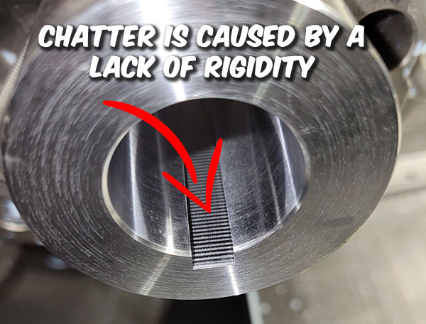
Is there chatter in the ceiling?
Chatter is caused by a lack of rigidity. Because our existing product line has been used successfully by thousands of shops since 2005, we can confidently say lack of rigidity will be caused by work-holding rigidity, part rigidity, machine rigidity, or fixture rigidity. Work holding rigidity can be solved by properly clamping your tool holder using one of the methods described in this blog post. Never use extensions, always use a stop behind the tool, never use VDI holders. Try to keep overhang down to a minimum. For larger keyways you will need a larger machine.
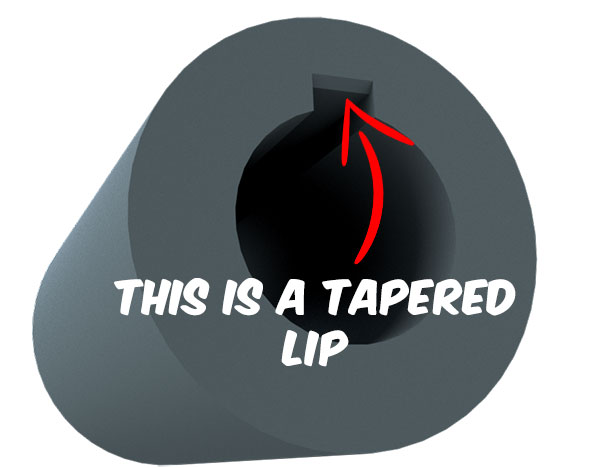
Do you have a Tapered Lip at the entrance of the keyway?
There are two things that will cause a tapered lip.
1. All CNC machines need room to accelerate. We suggest starting ⅝” in front of the part to allow space for the machine to get up to speed prior to making contact with the material. You may see a lip at the entrance of the part in the ceiling of the keyway if you are starting too close.
2. Another thing that can cause a tapered lip is a poorly mounted tool holder. In our Blog post titled “What is the best clamping method when mounting a CNC Broach Tool” we discuss the best methods for clamping a holder. We recommend that you do not mount a holder in a solid sleeve with only a single setscrew. We also mention that the setscrews must be inline with the insert so the tool pressure is in the same direction as the setscrews. A poorly mounted holder allows the tool to move in the sleeve. This movement causes a tapered lip
Is there a lip in the ceiling at the end of the keyway?
A lip in the ceiling of the keyway at the end of the stroke is usually caused by what we call the “Phantom Retraction”. Learn more about the Phantom Retraction here. This is caused by your machine prematurely retracting before reaching the programmed Z value due to the high feed rates used when broaching. This could also be a programming issue caused by the Z axis end point not being programmed to go far enough. Always be sure to program the cutting edge to go beyond the end of the material by at least .125″.
Do you have taper in the ceiling of the keyway that goes the entire length of the slot?
A tapered slot is usually a sign that the part is not parallel to the machine axis. Grab a dial indicator and sweep in the full length of the bore on your part to make sure it is clamped straight. This can also be caused by a headstock alignment issue.
Why did my insert pull out of the pocket?
1. We purposefully designed the insert to release from the pocket of the tool to protect the spindle when there’s not enough relief space. The insert MUST pass through the material into open air before pulling out of the cut. An insert will pull out of the pocket if the tool retracts radially while the cutting edge is still in the cut. Once the insert is clear of the material, retract radially into the bore, then retract out on Z.
2. Remember to broach far enough out the back of the part to allow for the Phantom Retraction. The Phantom retraction will retract the tool in the X or Y axis prior to reaching the Z depth and could cause the insert to pull up from the pocket. This can be prevented by programming the Z end point a minimum of .125″ past the end of the material.
3. If broaching a blind hole into a relief area, always make sure the relief is large enough so the corners of the insert clear the material on the final passes. We recommend that the broach relief extends .020-.030 beyond the corners of the insert. If the corners of the insert are still buried in the material when the program retracts in the X or Y axis, the insert could stick & pull up from the pocket.
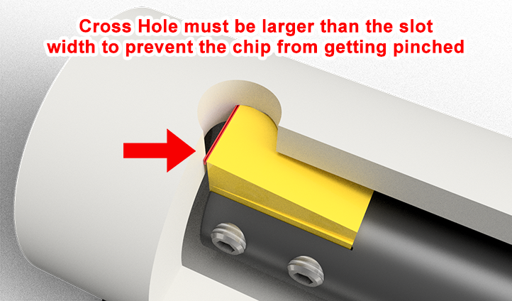
4. When broaching into a cross hole the hole must always be larger than the width of the keyway. If not, the curved opposing wall of the cross-hole will trap the chips causing them to pack into each other. This build up of chip causes excessive force on the machine and will eventually cause the insert to either break or pull out of the pocket.
5. An insert that has become overly dull could also pull out of the pocket. A dull cutting edge which is rounded or chipped could bind in the material causing it to stick or basically weld itself into the workpiece.
What Material are you broaching:
Feed rate and depth of cut must always be set based on the material you are broaching. Material hardness also needs to be taken into consideration. For example 4140 material hardness can range from 15-56 HRC. Information regarding Feed & DOC.
Are you broaching a blind hole or is it a through hole??
It’s very common for a customer to have a through hole with a blind slot. Always remember: If you are not broaching through the part you will always require a relief at the end of the cut to broach into. This is needed for chip evacuation. Without a proper space to push the chip into, the chips will pack at the end of the cut. Each pass will press more chips into the bottom of the keyway. With nowhere for the chip to go, the packed chips will eventually cause too much pressure and either chip or break the insert. If you are broaching in a bar feeder application remember: The broached slot is not through until you part off the barstock. You must treat bar feeder applications as if they are a blind hole.
How many slots are you getting per cutting edge?
Insert life is a difficult question to answer because we don’t know the rigidity of your setup. We wrote a blog post on improving your broach insert life. In aluminum your insert should last hours in the cut. In inconel your insert may only last minutes. This has to do with material properties, machine rigidity, tool rigidity, part rigidity, Depth of cut, feed rate, Coolant concentration, tool clamping method, and more.
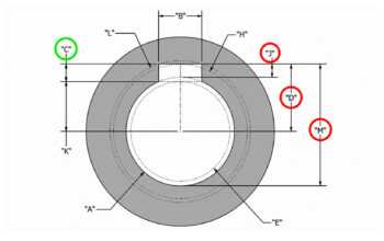
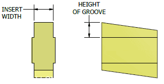
What is the radial depth (Height of Groove) and the length of cut?
The radial depth and length of cut of your keyway will affect cut time. For example if you have a 4140 part heat treated to 32 HRC with a .400 radial depth of cut and 8” stroke, each part will take approximately 25-35 minutes. If you’re only getting 4 parts per edge, you’re still getting 2 hours in the cut which isn’t bad for heat treated material (an estimated cycle time can be calculated on the Gcode Program Generator page)
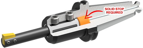
Do you have a stop behind the tool?
Just like drilling, there will be tool pressure applied to the cutting edge when broaching. This tool pressure will apply force to your tool holder which could cause it to push into the sleeve which you’ve mounted the broach holder in. We always recommend using a stop behind the tool to prevent this from happening.
How are you clamping the tool?
How you clamp the tool is the difference on whether it works or not. Incorrect clamping of the tool could cause chatter or taper. Read this blog post to learn more about the best clamping methods for mills & lathes.
What is your depth of cut?
The depth of cut you take should be set based on the material you are cutting. Too much depth of cut will cause taper and poor tool life. Too little depth of cut and insert will rub and burn out the sharp cutting edge. If a material has high shear strength, the forces required to cut through the material will be higher. As a result, taking a deeper cut may cause excessive tool wear, deformation, or breakage. This means that a smaller depth of cut may be necessary to maintain the rigidity of the cutting tool and prevent damage to the workpiece. Recommended feeds and depth of cuts.
What is your feed rate (IPM)?
Your feed rate should be set based on the material and the hardness of the material you are cutting. We recommend up to 550 IPM for aluminum and as low as 200 IPM for Inconel and hardened steel. Recommended feeds.
How far beyond the end of the slot are you programming your stop point?
We suggest programming the ending Z value a minimum of ⅛” beyond the end of the keyway. This is required due to the “Phantom Retraction”.
Are you pulling down & out of the keyway prior to retracting out on Z axis?
When programming the tool path for your machine you should always retract out of the keyway on the X or Y axis prior to retracting on the Z axis. We don’t recommend retracting on Z while still in the broached slot as this could cause chipping. When using our Gcode program generator the X/Y retraction is programmed in automatically.
How rigid is your part?
Thin walled parts can be problematic. Just like a bell, a thin walled part will ring when being broached causing chatter and possibly taper. Always keep your part as rigid as possible to help reduce or eliminate the ringing
What is your coolant concentration
Water based coolant is an acceptable lubrication for broaching. We recommend 10%-15% concentration
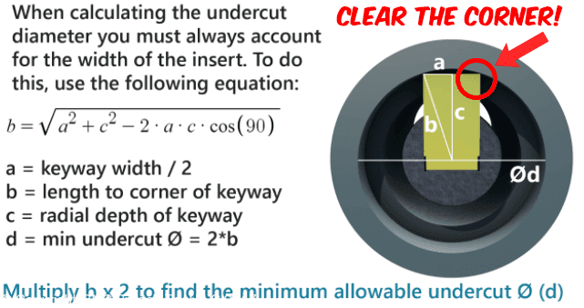
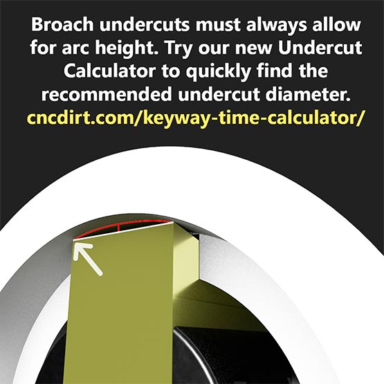
Is there enough room for chip evacuation?
Usually having a clearance groove or a cross hole to broach into is all you need. But there are some things to remember. First make sure your clearance groove is large enough to clear the 2 corners of the insert. The 2 outer corners of the insert have a longer radial distance from center than the midpoint of the insert. To Calculate the recommended broach clearance groove diameter see this calculator. Second, if you’re broaching a blind hole with no through hole for the chips to go, we recommend you broach horizontally so gravity acts as your friend and assists in chip evacuation. Always remember when broaching into a cross hole that the hole must be larger than the broached slot. For example for a .188″ wide keyway we recommend a Ø1/4″ (Ø.250″) Drill. See blind keyway broaching examples.
Have you dialed in the orientation of the tool so it is in line with the machine axis?
Always dial in the tool’s orientation to be in line with the machine’s axis. Learn more about dialing in the tool in our Keys to Using CNC Broach Tools blog post. If you are seeing uneven wear on your insert it is most likely caused by a tool which wasn’t properly dialed in.
Are you in a Lathe?
1. Are you using a split sleeve? Split sleeves are the best way to clamp the tool in a lathe. We don’t recommend using a solid sleeve with only one set screw.
2. Are you using a VDI holder? VDI holders can cause issues since they add extra length and hang further off the turret than a boring bar block.
3. Do you have a stop behind the tool? We always recommend using a stop behind the tool to prevent it from pushing in while broaching
4. When broaching in the main spindle while using a bar feeder (prior to cut off or transfer) you will need to broach as you would for a blind hole and add an undercut or a cross hole to broach into. This of course is not be required if you are broaching on the sub spindle after the part has already be cut off and transferred.
5. Touching off the X axis in a lathe is easy. If you have a touch probe in your lathe you can use it as you normally would. When touching off manually we recommend touching off on an outside diameter on the opposite side of centerline. When doing this you will need to touch off to a negative value
6. Have you dialed in the tool rotation so it is in line with the X axis? Learn more about dialing in the tool in our Keys to Using CNC Broach Tools blog post
Are you in a Mill?
1. What type of holder are you using to clamp the tool? Read more about our recommended clamping methods.
2. Are you in a Vertical mill or a Horizontal? This could affect chip evacuation when broaching blind holes.
3. Are you using Vise jaws? If so, where is the moveable jaw? Broaching with the tool pressure pushing towards the movable jaw could cause part movement. This should be checked with a mag base and indicator. We suggest broaching so the tool pressure is pushing into the solid jaw or 90° from the moveable jaw.
4. Is it a through hole application? Even a blind broach application can have a thru hole. All blind broach applications require a relief to broach into. The tool must always broach out the back side of the part or into a relief. The tool must never stop traveling in the Z axis while still in the cut.
5. What kind of clearance cut do you have? When broaching a blind hole we recommend either using a cross hole or a milled undercut to broach into
6. Is the clearance cut large enough so it clears the corner of the insert? Make sure your clearance groove is large enough to clear the two corners of the insert. The two outer corners of the insert have a longer radial distance from center than the midpoint of the insert. To Calculate the recommended broach clearance groove diameter see this calculator.
7. Have you dialed in the tool rotation so it is in line with the machine’s axis? Learn more about dialing in the tool in our Keys to Using CNC Broach Tools blog post
8. Have you dialed in your part? We recommend creating your Mill program from X0 Y0 and using the tool’s centerline print to determine the distance from the center of the tool to the cutting edge. Also note that when using the G-code program Generator the centerline dimension is automatically adjusted for
Here are the answers to our most commonly asked questions..
Why are my inserts chipping/breaking?
1. The main cause of chipping inserts is due to improper work-holding and lack of alignment. Be sure the insert is dialed in rotationally inline with the machine axis. Do not dial in the flat of the tool. Learn more about dialing in the tool in our Keys to Using CNC Broach Tools blog post
2. The second most common cause of a chipped insert is a programming issue. We recommend using our program generator which programs all the retractions automatically. We always recommend programming the Z start point 5/8″ in front of the part and the ending Z value to go beyond the end of the slot by at least 1/8″
3. The next most common cause is a rigidity issue, or a lack of clearance at the end of the keyway. Always program the tool path in a rectangular shaped move. Here is an example starting at our recommended 5/8″ in front of the part:
G00X1.000Z.625 (Rapid position in front of part)
G01 Z-2.125 (.125″ past the beyond the end of the material)
G00X.800 (Move down completely out of the slot),
G00Z.625 (Retract out of hole)
G00X1.001 (Move in an additional .001 for the next pass)
Also, if you’re broaching into a clearance groove, verify the clearance that you are broaching into is large enough to clear the corners of the insert. The two corners stick out further than the center of the insert. This can be calculated using our keyway broach cut time calculator.
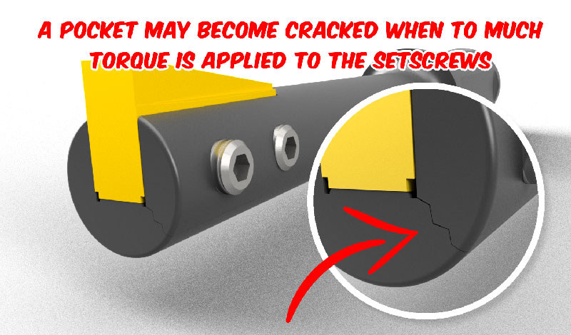
Why did the insert pocket crack in my holder?
When too much torque is applied to the set screw it could spread or even crack the pocket. It is important to avoid excessive torque on the set screws, as this can cause damage to the tool holder.
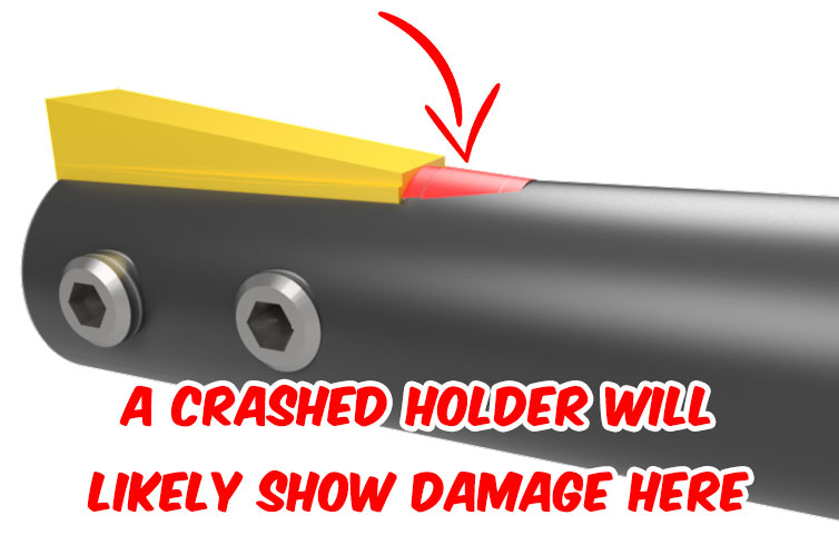
My Tool Bent / I have damage behind the pocket. What could’ve happened?
A bent tool means there was either an issue with the setup, an issue with the program, inadequate relief at the end of the keyway, or the insert was excessively worn out. Verify the tool was properly dialed in and touched off. Verify the program was written correctly, and verify the relief groove is large enough to clear the corners of the insert.
Why do my set screws keep loosening up?
Set screws wear out and flatten over time. If your set screws keep loosening up, we recommend you change them out. We supply extra set screws with every holder we sell in case you need them.
Another possible cause of the set screws loosening is severe chatter. See the section on chatter to eliminate this possibility.