Contact Us
 (877) 248-1631
There are many ways to mount a CNC Broach Tool holder in your CNC Lathe or Mill. In this blog post we are going to discuss the best method for achieving the most rigid setup possible. We will also teach you why you may be getting deflection or chatter in your current setup.
To start, let’s list some of the most common clamping methods we’ve seen over the years:
- Hydraulic holder
- Collet holder
- Solid Endmill Holder with set screws (Mill only)
- MTA Boring Bar Sleeve with set screws
- Split sleeve (Lathe only)
- Solid sleeve (Lathe only)
For each of the clamping methods listed above, we always recommend using a physical stop against the butt of the tool to prevent it from pushing in while broaching.
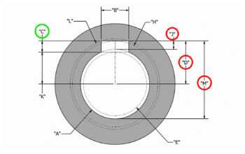
Most shanks on our tool holders are Ø.750 inch so we will be focusing on this size, however you can apply this same concept to all of our holders.
The best way to visualize clamping on a cylindrical shank is to unwrap the cylinder and view it as a flat sheet….
Now that we have an unwrapped view, let’s compare the surface contact between the different clamping methods listed above.
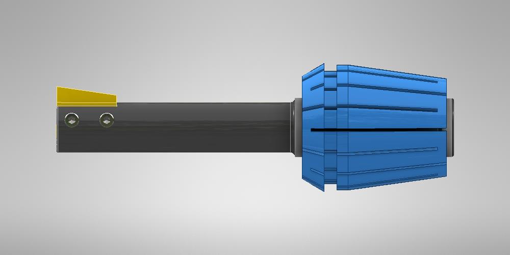
A Hydraulic holder provides the best surface contact to the shank of the tool in milling applications. It applies even clamping pressure around the entire shank of the tool. It also makes it easy to dial in the rotation of the tool when setting up.
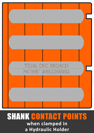
(View = Unwrapped 3/4″ tool shank)
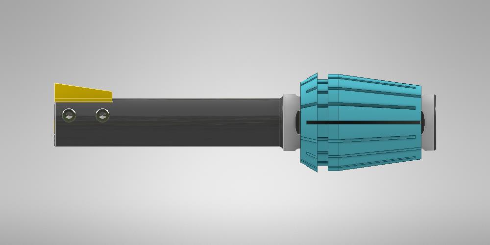
ER40 collets provide adequate clamping along most of the tool shank. When using ER40 collets, always use stubby holders without extensions when possible. One thing to keep in mind when selecting a collet holder is that the broach tool will most likely rotate when tightening the collet nut. This could make it more difficult to dial in the rotation of the tool when setting up.
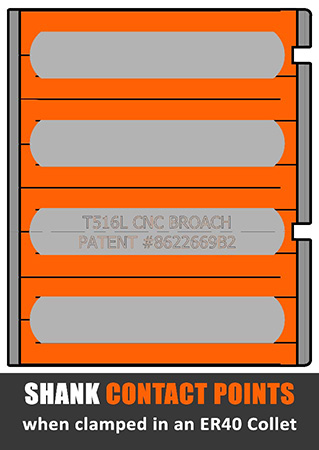
(View = Unwrapped 3/4″ tool shank)
An ER32 collet is fairly short at only 1.58″ inches long. These work well for narrow keyway tools, but are not recommended for keyways wider than 1/4″. Since an ER32 collet is shorter than the milled flats on the tool, it will clamp over the top of the flats as shown below. This is not an optimum situation. Another thing to keep in mind when selecting a collet holder is that the broach tool will most likely rotate when tightening the collet nut. This will make it more difficult to dial in the rotation of the tool when setting up.
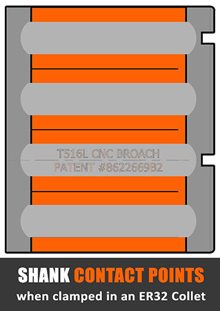
(View = Unwrapped 3/4″ tool shank)
A solid endmill holder with two set screws provides the second least surface contact to the shank of the tool. With two set screws clamped on a flat, there are 4 contact areas as shown in the image below. The 2 set screws apply pressure to the shank of the tool which then makes contact against the opposite side of the shank on both sides of the milled flat. When mounting a broach tool in a solid holder like this one, always orientate the set screws as shown below. Always tighten the set screws so they are in line with the top of the insert. Mounting like this keeps the clamping force in line with the tool pressure when broaching.
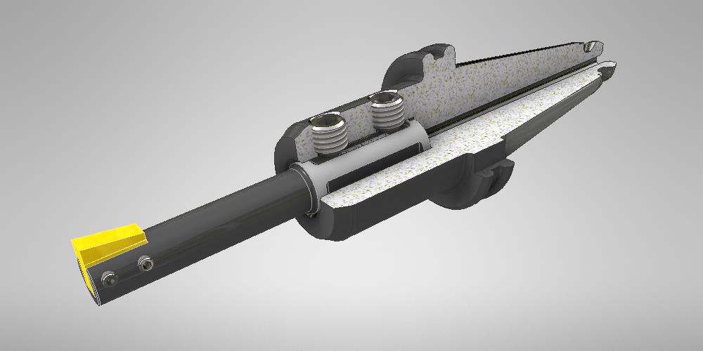
(View = Unwrapped 3/4″ tool shank)
A solid endmill holder with a single set screw provides minimal surface contact to the shank of the tool. With one set screw clamped on the flat (in line with the insert), there are only 3 contact points as shown in the image below. The one set screw forces the shank of the tool to make contact against the opposite side of the shank on both sides of the milled flat. The 3 contact areas are shown in orange below.
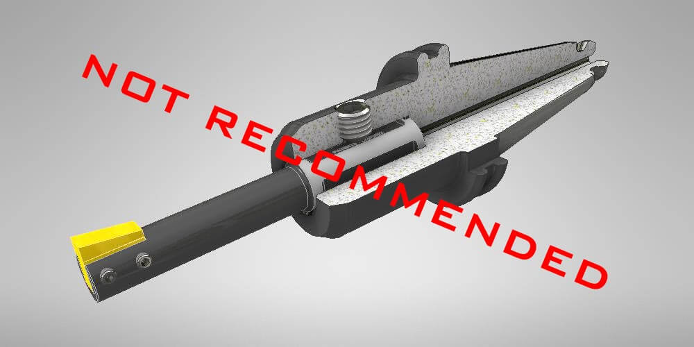
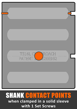
(View = Unwrapped 3/4″ tool shank)
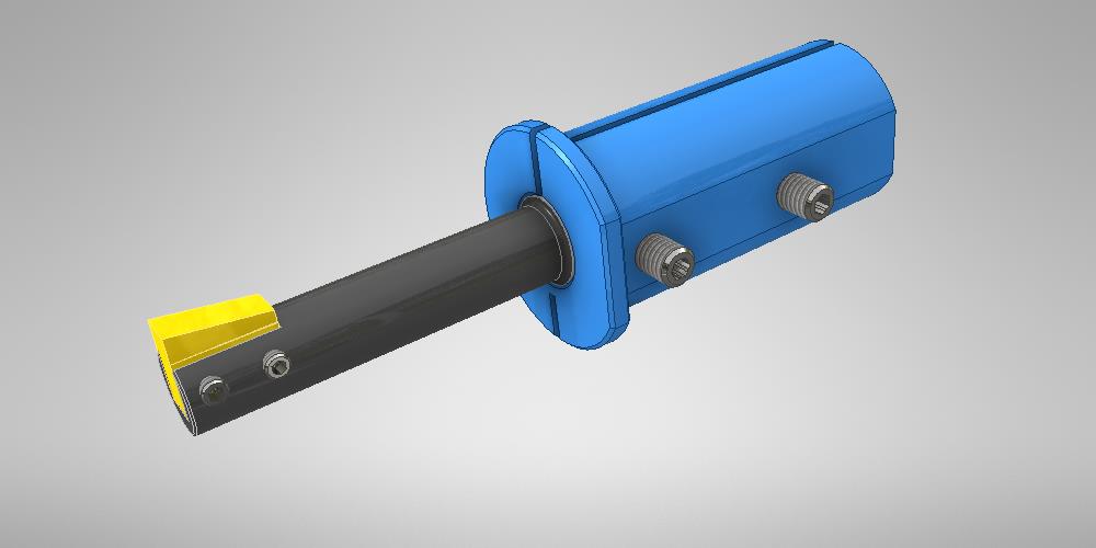
A solid MTA sleeve with eight set screws provides great contact to the shank of the tool. With eight set screws clamped on the flat, there are multiple contact areas as shown in the image below. This makes for a very rigid setup when clamped properly in the boring bar block. The 8 contact areas are shown in orange below. Learn more about MTA holders.
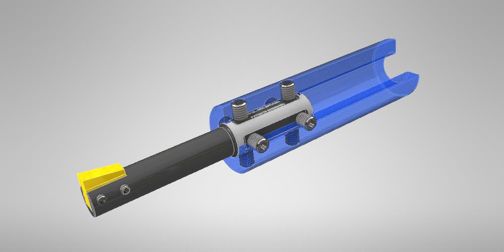
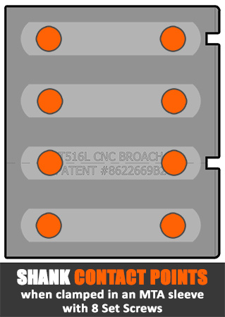
(View = Unwrapped 3/4″ tool shank)
A split lathe sleeve with two set screws provides excellent contact with the shank of the tool when in a CNC lathe. (The only thing better than a split sleeve in a lathe is a split block boring bar holder in combination with a split sleeve). Learn more about split sleeves.
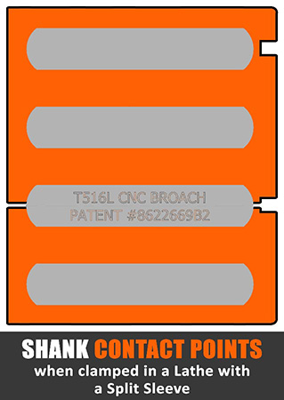
(View = Unwrapped 3/4″ tool shank)
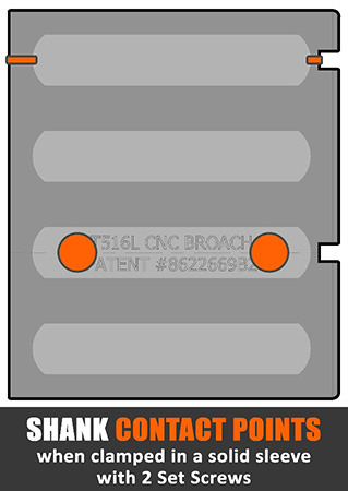
A solid lathe sleeve with two set screws provides minimal contact to the shank of the tool. With two set screws clamped on the flat (90 degrees from the insert), there are only 4 contact areas as shown in the image below. The 2 set screws apply pressure to the shank of the tool which then makes contact against the opposite side of the shank on both sides of the milled flat. When mounting a broach tool in a solid holder like this one, the set screws will not be oriented inline with the top of the insert. The clamping force is not in line with the tool pressure when broaching. This could allow the tool to rock slightly inside the sleeve once tool pressure is applied
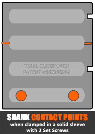
(View = Unwrapped 3/4″ tool shank)
Hopefully this helps visualize the surface contact between the many different clamping methods which could be used when broaching. To learn more about the set up process and for more information regarding split sleeves and hydraulic holders see our blog post titled “Keys to Using CNC Broach Tools“. Following this guide will maximize rigidity which should help improve tool life.