 Contact Us
 (877) 248-1631
The Design of CNC Broach Tools and Inserts are Proprietary and Protected by USA Patent #8,622,669,B2
KEYS TO PROGRAMMING CNC BROACHING
For Informational Purposes Only

CNC Lathe broaching and CNC mill broaching are great methods of completing the slotting process and avoiding the cost other expensive Broaching Systems. This guide will walk you through the basic steps of what it takes to get a CNC machine broaching your parts.
TIP: The code examples used in the guide will be that of FANUC, and YASNAC (Haas). The purpose of the guide is not to give you the codes you need but the concept behind what it takes to program tool path. If your codes are machine specific you will be able to locate and use them following this platform.
Locking the tool or material from rotation.
Prior to broaching you will need to stop the spindle from turning. On a lathe this means the part must be stopped from spinning. On a mill it means the tool will be stopped. This is generally performed by programming a M05.
CNC LATHE BROACHING:
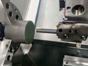
The first thing you’ll need to do prior to broaching in a CNC lathe is to stop the spindle. This can usually be done with an M05 command. Once the spindle has stopped you’ll need to orientate your spindle. This can usually be done with an M19 or a C axis command. Locking the spindle using the spindle brake can also be performed to increase positional accuracy. Now that the spindle has been stopped and oriented, we now need to set the feed-rate mode so we can feed while the spindle is off. To do this you must change the FEED units from G99 (inches per revolution) to G98 ( inches per minute).
TIP: Make sure you change back to G99 after you are done broaching.
The cutting motion of the Broaching tool.
Always follow the KEYS TO USING CNC BROACH TOOLS for tips & tricks on setting up the broach tool and to learn the fundamentals of slotting, such as clearance reliefs, material clearances, etc.. Now that the spindle is locked in position it’s time to start the cutting motion of the broach.
TIP: There are many ways to make the tool path. The examples below are probably the easiest to manipulate and require the least amount of typing. You can also try our patented CNC Broach Tools Program Generator. The Program Generator does the majority of the work for you.
The motion of the tool in the lathe is identical to the motion of the tool in the mill. However, you will need to consider that the lathe is moving on a diametrical value in the X direction and is not one to one. A .002” offset on a lathe only moves the tool by .001”, so when taking a .001” (depth of cut) pass with a broaching tool, you will need to program the tool to shift .002” on diameter.
Since it is easier to set the offset in the lathe to the tip of the tool, you should create the program to cut using the tip of the insert. This allows you to adjust the final cutting size with the X wear offset as normal. First position the tool in front of the part on the X & Z axis. Touch off the Z axis as normal on the front of the part. Setting the X offset using the tool tip on the inside diameter can be difficult because the corners of the square insert touch before the center of the insert. You can get around this by bringing the tool below center and touching off on the OD of the part. If the outside diameter is Ø3.000 you’ll need to touch it off to a negative three inches (Ø-3.000).
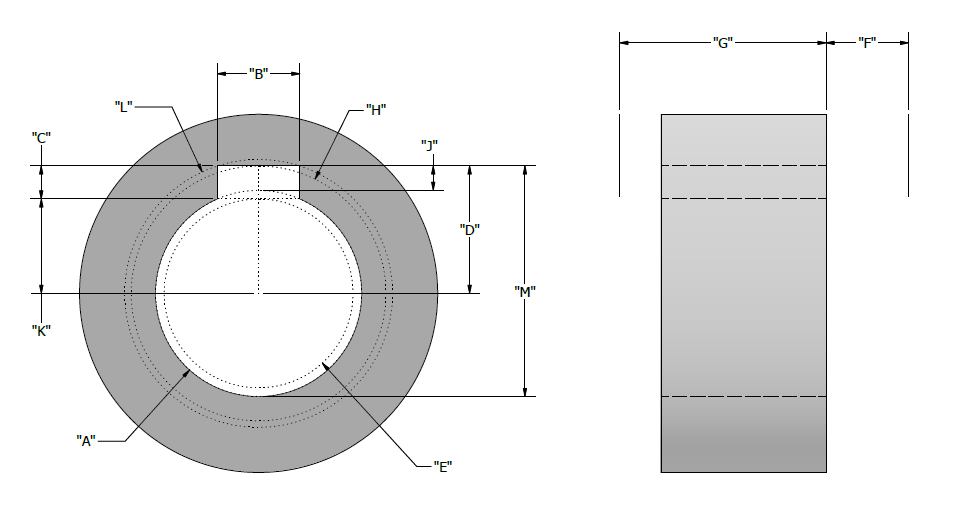
The X diameter programmed start point value will need to be calculated to allow for the width of the insert. Take a look at the image below. Notice how the “E” bore dimension is smaller than the “A” bore dimension? Diameter “E” allows for the width of the insert. Let’s say the Bore is Ø2.000, the keyway is .377”, the radial depth of the keyway is .200”, and the stroke length is 1.000”. The actual start diameter will be Ø1.9641” in this scenario (This can be calculated automatically when using our online program generator). In the main program, rapid the tool into position about .400 away from the front of the part and rapid to the calculated diameter:
Here is an example of a Lathe Sub-program. The bore in this example is Ø2.000. The programmed diameter has been adjusted to X1.9641 to allow for the corners of the .377 wide insert. This program takes 100 passes with a .002 depth of cut (programmed .004″ per pass in a lathe due to diametral value)
M19;
G00 G98 X1.9641 Z.400;  (Remember the G98 feed per min code)
M98 P500 L100;          (The same L and or 2 digits format prior works like the mill too)
Once the M98 line is read by the control, it then switches to program #500 and repeats 100 times.
G00 U.004;          (The incremental X move is the depth of cut .004 on DIA is .002 radially)
G01 Z-1.000 F100.;  (Cutting stroke in to bore)
G00 U-.500;         (Retract out of keyway, must be larger than double the Radial depth)
G00 Z.400;          (Stroke of tool out of bore)
G00 U.500;          (Repositions tool back to last depth of cut)
M99;                (Repeats sub program)
TIP: Remember to change back to G99 after the M98 line. Also, remember that the U retract amount must be larger than double the radial depth. For example, our keyway was .200” radially so to get the broach tool all the way out of the keyway we would have to retract more than .400”, that’s why we used .500” as the retract value. Be careful when using this program format if your bore diameter doesn’t allow for the full retract on the first pass. For example, the min bore diameter allowed for the T38L tool is Ø1.000. If you are using the T38L and are broaching in a Ø1.000” bore, you will not have room to retract .500”. In this case you should consider using the Program Generator to export a long program. This will create every line of code which can be pasted into your main program.
Also keep in mind the number of repeating times of the program will be proportional to the depth of cut. For example, our bore is Ø2.000 dia. With a keyway radial depth of .200” the final size of the keyway would be Ø2.400 if the keyway was on both sides, which it is not. Now you can see the depth of cut U.004” moves the tool incrementally .004” on a DIA. every pass 100 times. So .004” X 100 equals .400 which gives us a Ø2.400 end point for the broach tool.
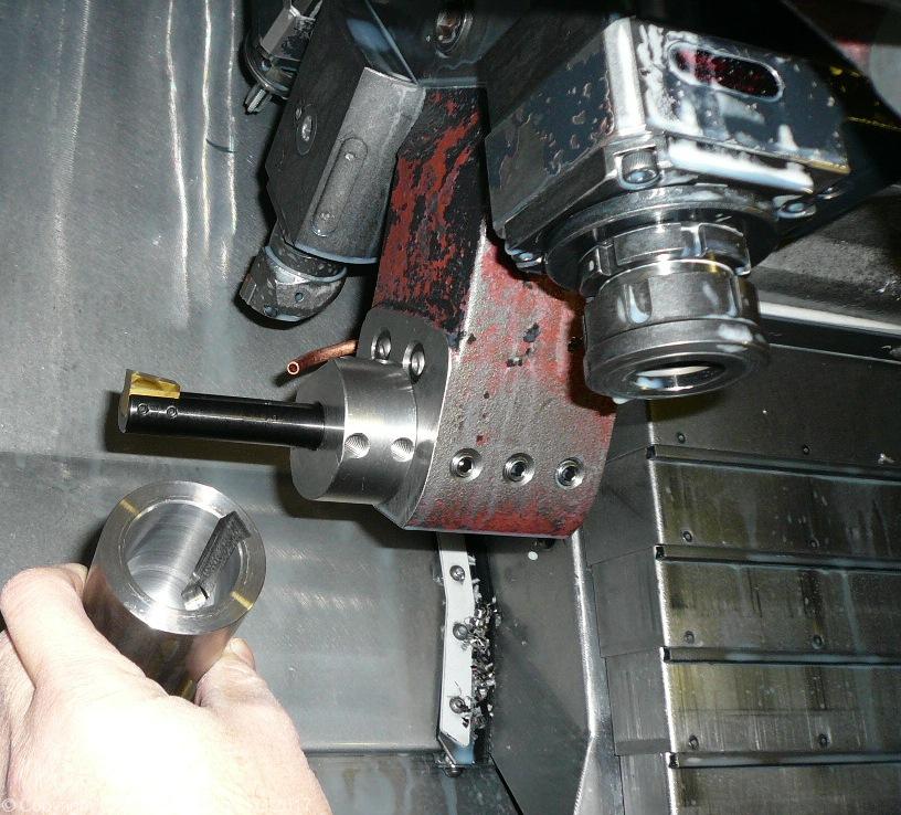
CNC MILL BROACHING:
The broach tool must be locked from spinning. A common way to achieve this is to orientate the spindle with an “M19”. Depending on the options your machine has, you may change the spindle orientation with a P or R on a Haas, or S on a Fanuc. These letters specify the angle. For example:
M19 P20 (Haas orientation adjustment - Rounds to nearest degree)
M19 R20.50 (Haas orientation adjustment - rounds to 2 place or 4 place decimal)
M19 S15.0 (Fanuc orientation adjustment)
M19 RS=65.2 (Okuma MV560 orientation adjustment)
M19; SPOS=25.0; (Siemens Control, two separate lines)
TIP: Some (not all) mills will alarm out once you try to FEED the tool with the spindle off, most (not all) have an M code that you can use to disable this safety feature. If no M code is available you can orientate the spindle to lock it in position, then start it again but at 0 RPM. For example: M19; M03 S0 ;
The example shown is as if the keyway is located in the 12 o’clock position. The program work offset has been set to the centerline of the bore. This is a very simple way to write the code for the broach. You can write the code off of the centerline of the part. Then use a different work offset for the broaching operation to manipulate the Y position to get and maintain the correct keyway depth. Let’s say the radial depth of the keyway is .200” and the stroke length is 1” inch. First position the tool at X0 Y0 and about .400 above the surface of the part. Then utilizing a sub program, incrementally move the tool in, down, out, back up, then in again, and repeat. The main program will have the lines leading up to the sub as follows:
M19;             (Orientate spindle)
G00 X0 Y0 Z.4;   (Rapid into Position on X Y and Z)
M98 P500 L100;   (M98 calls sub-program #500 100 times)
TIP: The L is the number of times to repeat the sub program (no decimal). If L does not work on your machine, the 1st set of digits after the P will be the repeat amount. For example “M98 P100500” is sub-program number 500 repeated 100 times.
TIP: The Program Generator creates the program off the centerline of the part and automatically adjusts the program centerline based on the tool chosen. This makes it easy so only a single work coordinate is required
Once the control gets to the M98 line it will change to the sub program which is as follows:
G00 G91 Y.002 ;       (This 1st move in Y is the depth of cut per pass)
G90 G01 Z-1.0 F100.;  (This is the cutting stroke down)
G00 G91 Y-.300 ;      (Retract, the Y must be greater than the radial depth of keyway)
G00 G90 Z.4 ;  	      (Stroke up out of bore)
G91 Y.300 ;  	      (Repositions the tool back to where the last depth of cut was taken)
M99 ;     	      (Restart the sub program)
TIP: Be sure to add a G90 after the M98 line to put the machine back into absolute mode. Also, to determine the L value, divide radial depth by depth per pass. For example, our radial depth is .200” and we have a depth of cut of .002” (.200” ÷ .002” = 100 = L)
ADVANCED CNC BROACH PROGRAMMING TIPS
SPINDLE ORIENTATION:
This method will work for mills that do not have the option to orientate the spindle to a designated degree by way of G or M code command. The following code can be used in place of the M19 in any mill template. You will then be able to have more control over what position the tool is in, in order to make it aligned with the broach you are trying to cut. The codes are below and the explanation and use will follow.
(Delete the M19 on any mill template and replace with the following)
M19
M03 S10
G04 P500
M03 S0
Explanation:
There is now 4 lines replacing 1 line.
- The 1st line M19 will lock the spindle in the tool change position, this is important since we want the spindle to begin its rotation from the same position every time.
- The 2nd line “M03 S10” will start the spindle rotating at a very slow RPM
- The 3rd line “G04 P500” is a dwell code. This is like an egg timer to the machine the code is non modal so will automatically cancel itself once the time has expired. (NOTE: the P is the time to wait. NO DECIMAL IS IMPORTANT, the time is in milliseconds.
- The 4th and last line “M03 S0” will then change the RPM of the spindle to 0 thus locking the spindle in whatever position it would be in after a rotation of 500 milliseconds.
HOW TO USE:
We recommend making a program with just the 4 lines in it. Then once you have installed your CNC Broach Tool in the spindle run the program with just the 4 lines. Take note at what position the tool has stopped in. The only number you will have to change is the time (which is the P value). Keep adjusting the P value until the broach is aligned in the desired direction close by eye. Then proceed to indicate the tool tip and tweak the P value until the indication is good. Now enter the same P value that worked in the program you are going to run the part with.

For Informational Purposes Only