 Contact Us
 (877) 248-1631

- We recommend mounting the tool using a split sleeve in a lathe or a hydraulic holder in a mill. Always use a backstop behind the tool.
- Retract in X before pulling out in Z – Never retract through the keyway.
- Start the Z stroke 0.625″ in front of the part so the Z AXIS reaches full speed.
- End the Z stroke at least 0.125″ past the material to avoid the “Phantom Retraction” (See last page)
- Program the First pass so the insert corners clear the bore. Always allow for the full insert width
There are many ways to mount a CNC Broach Tool holder in your CNC Lathe or Mill.
Here are some of the most common clamping methods we’ve seen over the years:
- Hydraulic holder
- Collet holder
- Solid End Mill Holder with set screws (Mill only)
- MTA Boring Bar Sleeve with set screws
- Split sleeve (Lathe only)
- Solid sleeve (Lathe only)
A Hydraulic holder is the best method.
Collet holders work well as long as the collet is longer than the milled flat. We do not recommend an ER32 since it is only 1.57” long
Solid End mill holders work well however they must have at a minimum of two set screws. A single set screw is not recommended
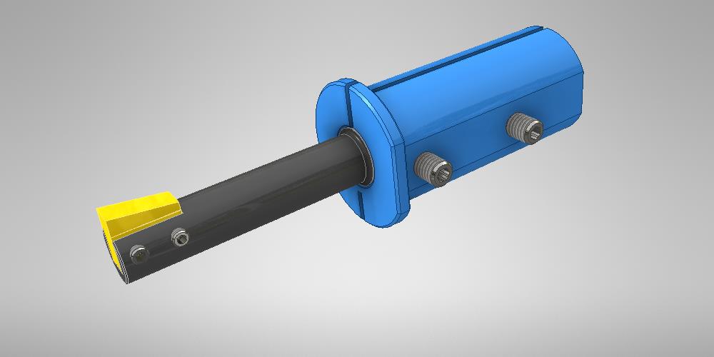
In a Lathe we recommend a split sleeve over a solid sleeve. You must have at a minimum of two set screws
Always use a stop behind the tool
Setting up a broach tool to cut in a lathe:
Always dial in the tool’s orientation to be in line with the X axis: To do this, first remove the insert from the holder and find a gauge block that will fit into the insert pocket (any gauge block smaller than the pocket width will work). Lightly snug the set screws down just enough to hold the gauge block in place. Dial the gauge block in as shown in the image below. We recommend dialing in to within .0005”. Always dial in the pocket for the best accuracy
Once the tool has been dialed in rotationally along the X axis, dial in the front diameter of the tool in the Y axis. We recommend dialing this in to within .0005” as well. Once dialed in, replace the insert. For recommended torque specifications, please refer to the centerline drawings available on the website.
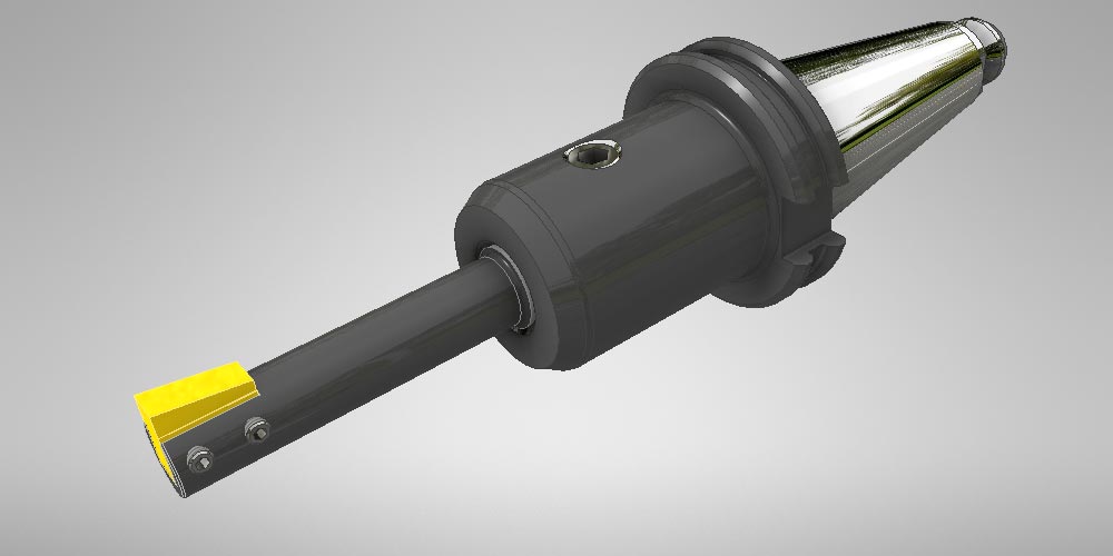
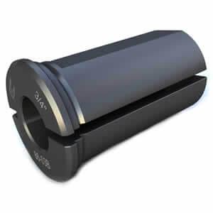
Mounting the tool: We recommend mounting the tool in a boring bar sleeve. Split sleeves have the most accurate and solid connection when clamping on the shank of our tool. This is because they contact a full 360 degrees around the shank. We recommend using Rovi Products B style split sleeves. Learn why we recommend this clamping method.
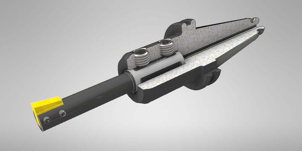
Solid sleeves can work as well, however when solid sleeves become worn out they are not nearly as accurate or rigid. Slop in the boring bar sleeve could allow the tool to chatter and deflect off center. MTA Boring bar sleeves with two sets of set screws 90° apart work best when using solid sleeves. This gives you 3 line clamping (the line formed by the two sets of set screws and the opposite side of the boring bar sleeve bore) and is the 2nd best option.
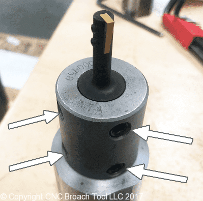
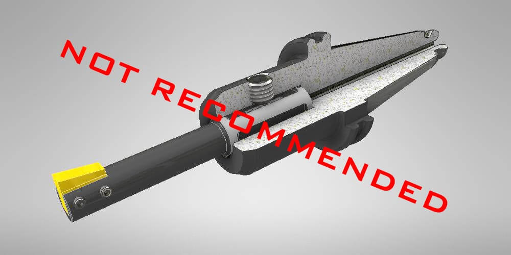
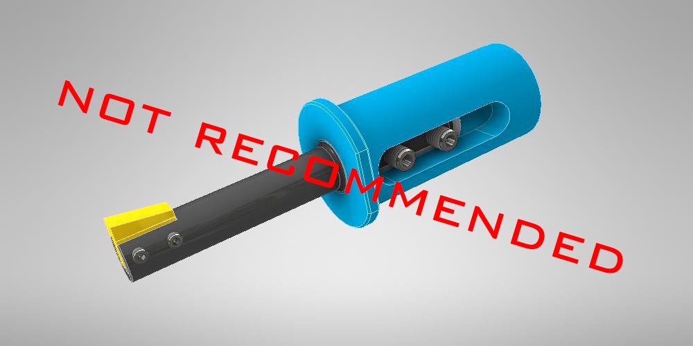
If using a solid sleeve with only 2 set screws:
- Always use a sleeve with a minimum of 2 set screws in line with our insert (not 90 degrees to the insert) to prevent taper in the ceiling of the keyway.
- Never use a solid sleeve with only a single set screw. This creates a pivot point which allows the tool to deflect.
- If your boring bar sleeve set screws do not orient onto our factory flat, you will need a different sleeve.
- Always use a stop behind the butt of the tool to prevent it from slipping in the boring bar sleeve.
Setting up a broach tool to cut in a mill:
Mounting the tool: Our first choice when clamping a broach tool in your mill is to use a Hydraulic holder. Learn why we recommend using a hydraulic holder. If this is not an option due to expense, a solid holder with a minimum of 2 set screws will work as well. Always use a solid back stop behind the tool to prevent it from pushing back. Rigidity is always key when broaching so we recommend using a CAT40/50/60 connection or Big-Plus connection. We only recommend using HSK when it is type A, and we do not recommend using a Capto connection.
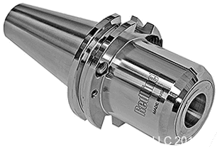
- How you clamp our tool is the difference between whether it works or not.
- Never use a holder with just one set screw as it will create a pivot point and will most likely chatter.
Always dial in the tool’s orientation to be in line with either the X or Y axis: To do this, first remove the insert from the holder and find a gauge block that will fit into the insert pocket (any gauge block smaller than the pocket width will work). Lightly snug the set screws down just enough to hold the gauge block in place. Load the tool holder into the machine and orientate the tool using an M19. Once the spindle has been oriented, dial the gauge block into .0005” along the X or Y axis.
Once the tool is dialed in, replace the insert. Do not over tighten the set screws as this could cause the pocket to crack or spread open. For recommended torque specifications, please refer to the centerline drawings.
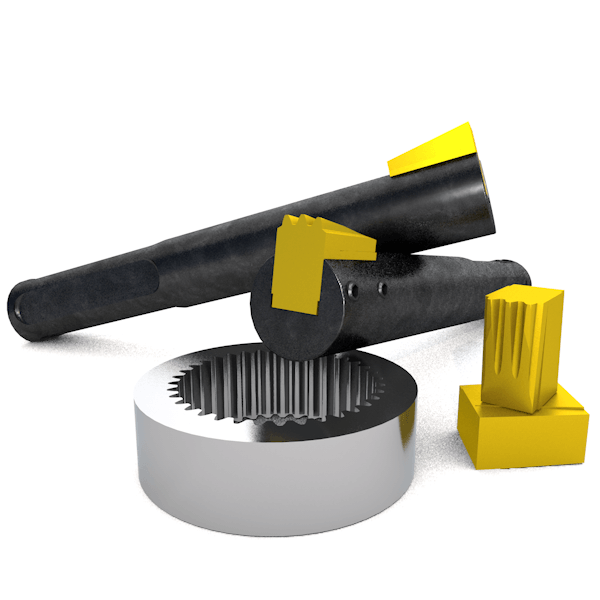
Blind holes, Blind Keyways, Thru holes, Clearance grooves, & Cross holes
When broaching a keyway, the cutting tool must pass completely through the material into open air before retracting out of the cut to prepare for the next cut. This is easy when broaching completely through a part, but can be tricky when broaching a blind keyway.
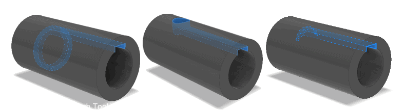
Turned Undercut Cross Hole Milled Undercut
Warning – If you have a through keyway application but are broaching bar stock prior to it being parted off, you will still need clearance as shown above
Blind keyways are tricky and crashes happen! You must have an appropriate groove or cross hole relief at the end of the cut
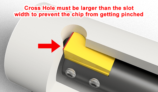
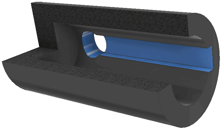
The pictures above show 3 options when dealing with a blind keyway. As we mentioned earlier, the edge of the insert must continue straight and must pass through the material into open air before pulling out of the cut. If the tool stops accelerating forward without first passing through into a clearance relief, the chips will be compacted in front of the tool and will cause issues. Therefore, you must use either an undercut, a crosshole, or a milled slot /undercut.
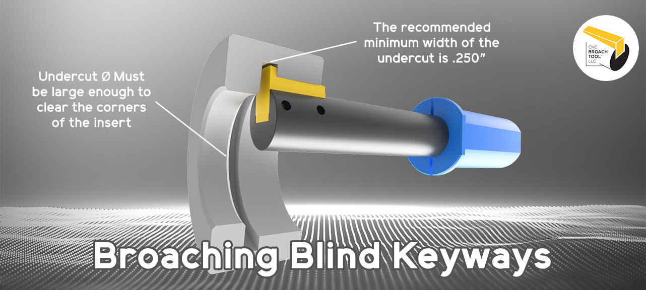
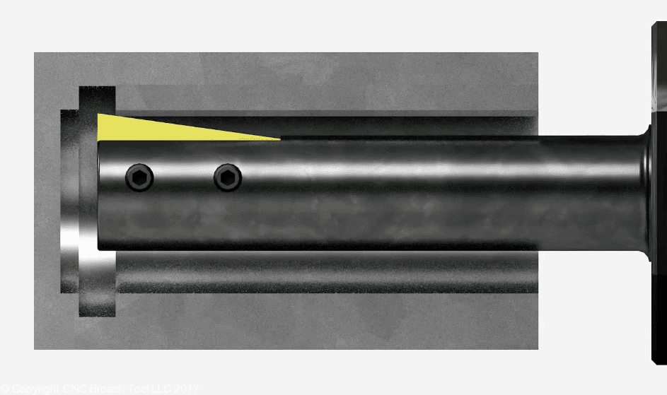
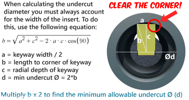
Turned Undercut: This of course is the best option when in a lathe. We recommend the clearance groove to be at least .250” wide min (to allow for Z axis deceleration) and the diameter of the groove must be calculated to allow for the keyway width and radial depth. Our online Blind Keyway Undercut calculator can be found here: https://cncdirt.com/keyway-time-calculator/
Cross hole: A drilled cross hole is a good option in both turning and milling applications. A crosshole can be drilled from the outside of the part. When drilling, we recommend using a drill which is at least 25% larger in diameter than the keyway width to allow for proper clearance. For example, a .250” wide keyway should broach into a cross hole that is at least Ø.3125”.
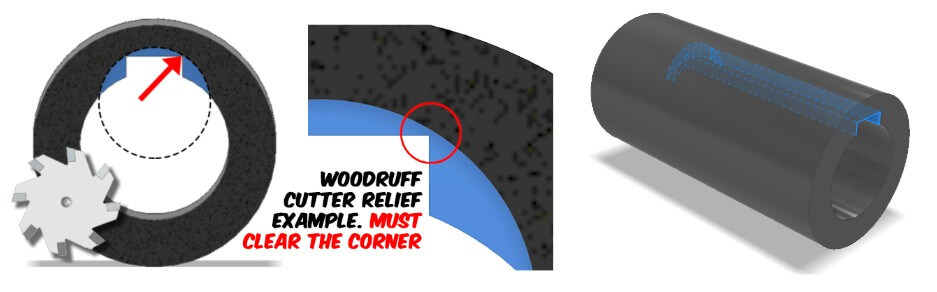
Milled Slot /Undercut: If a turned undercut or a drilled hole isn’t an option, we recommend milling a slot using a woodruff keyseat cutter. Just like the turned undercut, we recommend the clearance cut to be at least .250” wide (to allow for Z axis deceleration). The radial placement of the slot must be calculated to allow for the keyway width and radial depth of the keyway. There must always be clearance in the corners as shown below.
Programming:
We have tons of resources on our website to help you write your program. We even offer machine specific templates to make it easy. Here are our main “keys” to programming:
- Your first pass must allow for the insert width. If your bore is Ø.750″, your first pass cannot start at Ø.750″.
- Program the tool to drop down completely out of the keyway on the retraction. Do not retract backwards through the keyway
- We recommend taking .0008”-.0015” per pass, dependent on material. Feeds and speeds can be found here
- We recommend feeding the tool at 250-450 IPM (inches per minute) on the rough passes and 150 IPM for the final finish pass. Feeds and speeds can be found here
- Program the G01 starting point of the cut to be .625” in front of the part. This allows your machine enough space to completely accelerate to the programmed feed rate
- Program the end of the cut to be at least .125” past the end of the keyway. This allows space for the machine to decelerate in the relief area instead of decelerating while in the cut. It also allows for the Phantom Retraction.
- Once the cutter has passed through the material, program the cutter to pull completely down & out of the keyway prior to retracting out of the hole.
- We recommend using water soluble coolant with 12-15% concentration, especially for stainless and other hard to machine materials.
- Most machines have a G-code for exact stop (e.g., G61 on Fanuc), which ensures positioning is reached before the next move. If there’s not enough room to decelerate and you see taper at the end of the keyway, try using this code. If unavailable, add a dwell at the end of the cut. To learn what causes taper at the end of your keyway, read our blog post titled “The Phantom Retraction“
Questions and answers:
Why did my insert pull out of the holder?
We designed the insert to release from the pocket of the tool to protect the spindle when there’s not enough relief space. The insert MUST pass through the material into open air before pulling out of the cut. If your insert came out, this is a clue that you either:
- Have a programming issue
- Don’t have enough relief space
- The chips aren’t evacuating the relief space and you’re pounding into them (Our tool design may have just saved your spindle)
Why is there taper at the end of the keyway?
The machine does not have enough room to decelerate in air and is pulling out of the cut prior to reaching the full depth. To fix this you can either program the tool to cut deeper in the Z axis, reduce the feedrate, add an exact stop g-code to your program, or add a dwell line after the Z end point. Taper can also result from poor workholding—always verify the part isn’t moving or flexing during the cut.
Changing set screws on my CNC Broach Tool
The set screws can wear down after a few months. If they appear to be flattened they may not grip properly. For recommended torque specifications, please refer to the centerline drawings available on our website.
Will CNC Broach Tools write my CNC program for me?
We do not have a full time programmer on staff. Instead, we offer our clients a free proprietary Lathe & Mill Program Generator which can be found in the programming section of our website. Just enter your part parameters, copy the code, and paste it into your program. We also offer machine specific programming templates. Check out: https://cncbroachtools.com/category/cnc-broach-programs/.
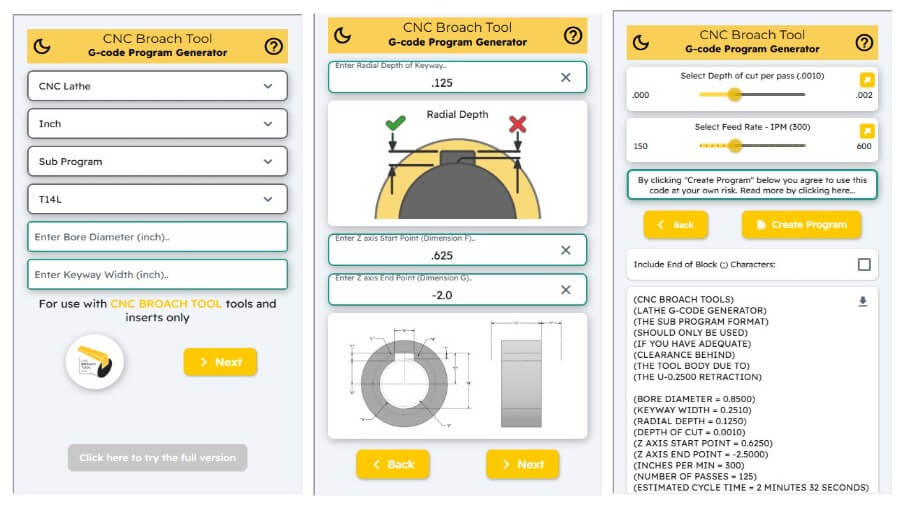
You can use our CNC broach G-Code Program Generator to export the G-code required for your broaching passes. This works for both CNC lathes and Mills
We also can connect you with a trusted associate who can help you overcome your programming/ technical hurdles for an hourly fee.
How many parts will I get per cutting edge?
One of the most asked questions we receive at CNC Broach Tools is in regards to broach insert life. For an in depth discussion on this we recommend you read our blog post titled “Insert Life of CNC Broaching systems“.
Will CNC Broach Tools create a custom shaped insert?
Yes, we have the ability to create custom inserts which include custom widths, custom splines, hexes, and others. These generally take 2-4 weeks to ship. Learn more at https://cncbroachtools.com/cnc-spline-broach/
More Q&A? Go to: https://cncbroachtools.com/cnc-broaching-faq/
Special Spline Inserts:
All Spline Broach Inserts are a Special Grind with a 3pc minimum order quantity. Spline Inserts fit our standard Keyway Slotting Tools, and have TWO carbide cutting edges. Please provide a blueprint, DXF, or 3D model when requesting a quote.
- CNC Broach Tools will review your print and, if a spline broach insert is suitable, provide a quote
- Upon order placement, we’ll send an approval drawing for your review.
- After print approval, spline broach inserts ship in 21–28 days. An expedited option is available (7–10 days).
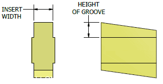
Understanding the Height of Groove (H.O.G) Dimension:
When using our keyway insert chart below, please always check the “Height of groove” dimension. This is how high the insert sticks up above the tool to get the radial depth (not length). This depth dimension is different than the “length” is not usually called out directly on drawings. It must be calculated. The “C” dimension in the image below shows exactly how this dimension is measured.
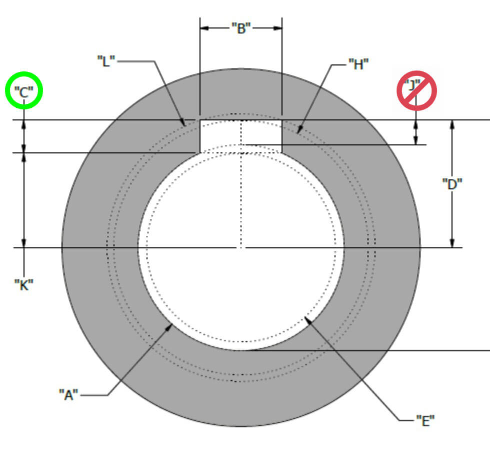
For clarity: A keyway or slot has three dimensions… 1) Width, 2) Length (axial), 3) Radial depth (Height of Groove or ceiling of the keyway)
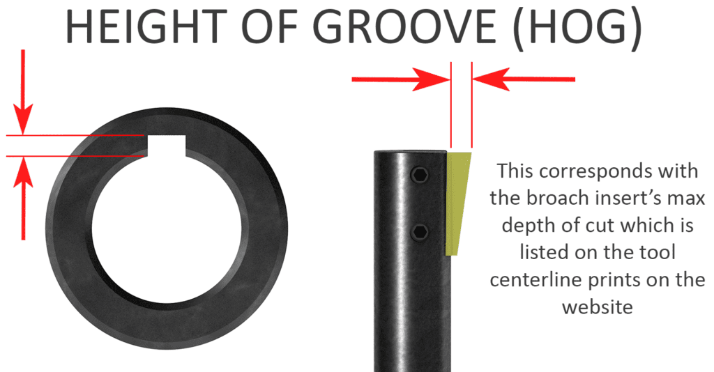
There are many important dimensions which apply to broaching. When we talk about “Radial Depth” or “Height of Groove”, we are referring to dimension “C” as shown above
Looking for more help? We’ve teamed up with the creator of CNC Machinist Calculator Ultra and added a Keyway Broach Program Generator into the app. Find it on your phone’s app store


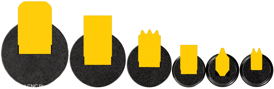
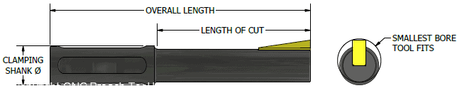
BROACH TOOL & KEYWAY BROACH INSERT DIMENSIONS
| Part No. | Holds Inserts For Keyway | Length of Cut (LOC) | Overall Length | Clamping Shank Diameter | Smallest Bore Tool Fits |
|---|---|---|---|---|---|
| T564L | 3/32", 2mm, 5/64", 1/16", and 1.5mm | 1.100" | 3.225" | 0.750" | 0.310" |
| T332L | 3/32" | 1.125" | 3.25" | 0.750" | 0.377" |
| T18L | 3mm or 1/8" | 1.575" | 3.7" | 0.750" | 0.500" |
| T158SM | 4mm or 5/32" | 1.575" | 3.7" | 0.750" | 0.466" |
| T4MML | 4mm or 5/32" | 2.375" | 4.5" | 0.750" | 0.575" |
| T316SM NEW | 3/16" | 1.870" | 4" | 0.750" | 0.600" |
| T316L | 3/16" | 2.620" | 4.75" | 0.750" | 0.600" |
| T5MML | 5mm | 2.625" | 4.75" | 0.750" | 0.600" |
| T6MML | 6mm or 15/64" | 2.940" | 5" | 0.750" | 0.745" |
| T14L | 1/4" | 2.940" | 5" | 0.750" | 0.835" |
| T516L | 8mm or 5/16" | 2.940" | 5" | 0.750" | 0.880" |
| T38L | 3/8" | 3.948" | 6" | 0.750" | 0.967" |
| T38SM NEW | 3/8" | 2.948" | 5" | 0.750" | 0.967" |
| T12L | 1/2" | 4.500" | 7" | 1.000" | 1.360" |
| T58L | 5/8" | 6.250" | 9" | 1.250" | 1.685" |
| T75L | 3/4" | 8.250 | 12" | 1.500" | 1.994" |
| For Keyway Width | Part Number | Insert Width Tolerance | Height of Groove (HOG) | Fits Broach Tool Holder |
|---|---|---|---|---|
| 1mm | N1MM | 0.041" +.001/-.000 | 0.052" | T564L |
| 1.5mm | Bi-59 | 0.059" +.001/-.000 | 0.052" | T564L |
| 1/16" | N116 | 0.064" +.001/-.000 | 0.052" | T564L |
| 5/64" | N564 | 0.079" +.001/-.000 | 0.052" | T564L |
| 2mm | Bi-080 | 0.080" +.001/-.000 | 0.052" | T564L |
| 3/32" | Bi-94 | 0.094" +.001/-.000 | 0.052" | T564L |
| 3/32" | N96 | 0.095" +.001/-.000 | 0.052" | T564L |
| 1/16" | N64 | 0.064" +.001/-.000 | 0.075" | T332L |
| 2mm | N2MM | 0.080" +.001/- .000 | 0.075" | T332L |
| 3/32" | N332 | 0.0955" +/- .0005 | 0.075" | T332L |
| 4mm or 5/32" | Bi-160SM | 0.160" +.001/-.000 | 0.100" | T158SM not T4MML |
| 3mm | N3MM | 0.1195" +.001/-.000 | 0.100" | T18L |
| 1/8" | N126 | 0.126"+.001/-.000 | 0.100" | T18L |
| 1/8" | N18 | 0.127 +.001/-.000 | 0.100" | T18L |
| 4mm or 5/32" | N4MM | 0.158" +.001/-.000 | 0.120" | T4MML |
| 3/16" | 3N3316 | 0.188 +.001/-.000 | 0.125" | T316L & T316SM |
| 3/16" | 1N1316 | 0.1885" +.001/-.000 | 0.125" | T316L & T316SM |
| 3/16" | 2N2316 | 0.190" +.001/-.000 | 0.125" | T316L & T316SM |
| 5mm | N198 | 0.198"+.001/-.000 | 0.125" | T5MML |
| 5mm | N5MM | 0.199" +.001/-.000 | 0.125" | T5MML |
| 6mm | N238 | 0.238"+.001/-.000 | 0.150" | T6MML |
| 6mm or 15/64" | N6MM | 0.239" +.001/-.000 | 0.150" | T6MML |
| 1/4" | N251 | 0.251"+.001/-.000 | 0.150" | T14L |
| 1/4" | N14 | 0.252" +.001/-.000 | 0.150" | T14L |
| 5/16" | N313 | 0.3135" +.001/-.000 | 0.200" | T516L |
| 5/16" | N516 | 0.3155" +.0005/-.0005 | 0.200" | T516L |
| 8mm | N316 | 0.3165" +.001/-.000 | 0.200" | T516L |
| 8mm | N8MM | 0.318" +.001/-.000 | 0.200" | T516L |
| 3/8" | N376 | 0.376" +.001/-.000 | 0.220" | T38L & T38SM |
| 3/8" | N38 | 0.377" +.001/-.000 | 0.220" | T38L & T38SM |
| 10mm | N394 | 0.394" +.001/-.000 | 0.280" | T12L |
| 7/16" | N439 | 0.439" +.001/-.000 | 0.280" | T12L |
| 12mm | N474 | 0.474" +.001/-.000 | 0.280" | T12L |
| 1/2" | N501 | 0.501" +.001/-.000 | 0.280" | T12L |
| 1/2" | N12 | 0.502" +.001/-.000 | 0.280" | T12L |
| 5/8" | N626 | 0.626" +.001/-.000 | 0.338" | T58L |
| 5/8" | N58 | 0.627" +.001/-.000 | 0.338" | T58L |
| 3/4" | N75 | 0.752" +.001/-.000 | 0.450" | T75L |
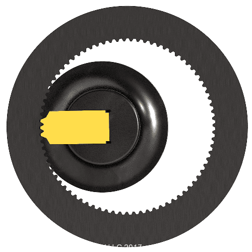
How to Program your CNC to cut a Keyway that is wider than your Broach Insert
Have you ever needed to broach a keyway, but then realized that the standard keyway widths offered by CNC Broach Tools won’t work for your keyway width tolerance? This usually isn’t an issue since CNC Broach Tools can create custom width grind inserts and ship them within 10-14 days. But, what if you need it sooner?
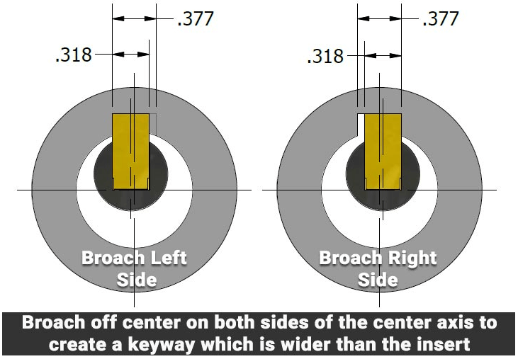
Look at the example above: To broach a 3/8″ wide keyway with your 5/16″ broach tool simply offset the tool off center. Program a complete broach cycle on both the left and right side of center. This can be done in any CNC Mill and can also be done in Lathes with Y axis capability. The example above shows our .318” wide insert broaching a .377” wide keyway. The first broach cycle is offset .0295” to the left side of center. The second broach cycle is offset .0295” to the right side of center.
Never exceed the Height of Groove Dimension when stepping over
Never exceed the maximum radial depth of the insert when stepping over to create a wider keyway.. The radial depth is also known as the Height of Groove (HOG) dimension. The example on the previous page works perfectly because the radial depth of the 3/8″ keyway is .1875″ and our N8MM (.318″) insert has a max radial depth of .200″.
Always be aware of the “Phantom Retraction”
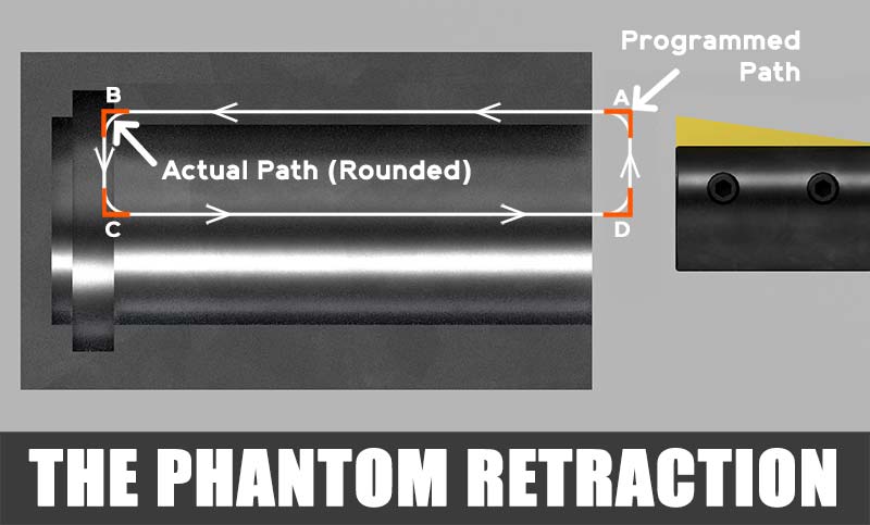
In CNC machining there is a default tolerance built into the control which permits the machine to round corners while performing a G01 feed move or a G00 rapid move. This rounding is used to help speed up your cycle without requiring the machine to stop at each axis move. The faster you’ve programmed the feed rate, the more your machine will round the corner. At CNC Broach Tools we refer to this as the Phantom Retraction. Most machines have a G code (G61 & G09) which is used to bypass this rounding.
Always program the Z end point a minimum of .200” beyond the end of the cut to prevent the Phantom Retraction! Read our blog post to learn more
Always check your drawing against the Broach Tool Size chart & let us know the part #’s you’d like quoted. When choosing a tool and insert you will need to know the following:
- Bore Diameter
- Length of Cut
- Key Width Tolerance
- Height of Groove Dimension

 |  |  |
Contact Us Today: Tel: (877) 248-1631Fax: (877) 410-7836Address:PO Box 569 Laguna Beach, CA 92652 |     |