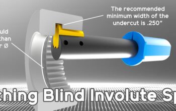
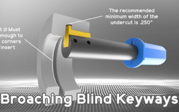
Broaching is one of the most efficient processes for creating precise internal features such as keyways and splines. Yet, tool life in broaching often seems unpredictable, with many shops relying on trial-and-error settings that can lead to premature wear or poor finishes. The real problem lies in a gap within traditional machining charts: they rarely account for the structural strength of the tool holding system.
To solve this, we’ve developed a rigorous, two-tiered method for calculating Depth of Cut (D.O.C.)—a method grounded in both material science and mechanical engineering. This approach allows machinists to set parameters that are not only optimized, but scientifically validated.
The Flaw in Conventional D.O.C. Tables
Most broaching recommendations are based only on the work material’s properties (like hardness or tensile strength) and the width of the cut. These are important factors, but conventional charts assume the holder and machine are perfectly rigid and limitless in strength.
In reality, every holder is an engineered structure with a defined strength capacity. Traditional methods overlook this fact, which can lead to settings that unintentionally push the system too hard.
The Physics of Precision: Smart Force Balancing
Our method calculates the ideal Depth of Cut by balancing two forces:
- The Required Cutting Force – how much force is needed to shear the material at a given depth.
- The Maximum Allowable Force – the engineered capacity of the tool holder system to handle that force without exceeding its design limits.
The guiding rule is simple:
The required cutting force must always remain within the allowable force capacity of the system.
This ensures every cut is safe, efficient, and fully optimized.
1. Maximum Allowable Force
The holder’s strength is determined using a classic cantilever beam calculation. This takes into account:
- Material Stiffness (Modulus of Elasticity, E) – for example, 29 × 10⁶ PSI for 17-4PH steel.
- Geometry (Moment of Inertia, I) – based on holder diameter and shape.
- Unsupported Length (L) – the effective length that carries the cutting force.
With a defined allowable displacement (the tolerance for movement), these inputs determine the maximum force the holder can sustain while maintaining stability and precision.
2. Required Cutting Force
The cutting force needed for broaching is calculated from two inputs:
- Material Resistance – measured by the material’s ultimate shear stress (τ).
- Cut Geometry – the engaged area of material, equal to Keyway Width × D.O.C.
Finding the Structural Limit
By comparing the two values, we calculate the maximum structurally supported Depth of Cut. This represents the upper limit that the system can support with confidence.
Conclusion: Precision by Design
By grounding Depth of Cut in real engineering principles, we eliminate guesswork and create a new standard for broaching. This method proves that the system is not only strong, but intelligently optimized. The results:
- Superior Tool Life – cutting within designed strength limits reduces stress on every edge.
- Optimal Surface Finish – consistent rigidity produces clean, precise features.
- Maximized Efficiency – pairing the engineered D.O.C. with optimized feed rates yields faster, safer cycle times.
With this approach, your broaching operations run at their smartest, strongest, and most predictable performance level.
 Contact Us
 (877) 248-1631
